
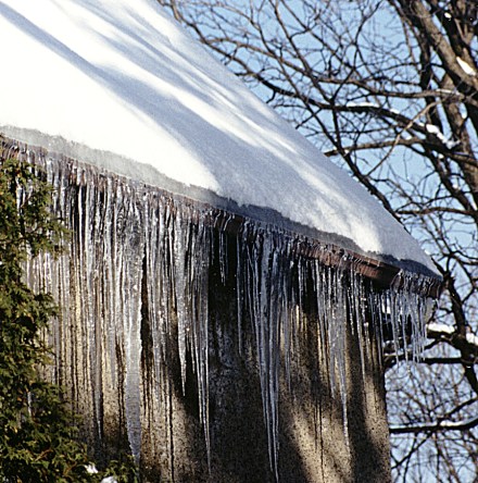
February and March are usually ice-dam season in the Montreal area. I’ve written before about ice dams What’s an “Ice Dam”? and Ice Dams – Cures, fixes and band-aids. and it’s time to look at what you need to do to make the problem go away.
The first thing to look at is the source of the problem, which is excessive heat transfer to the roof, the consequent melting of snow, and the freezing of the melt at the eaves and valleys.
This post will review the various components that contribute to the formation of ice dams, and will suggest a number of ways these can be corrected.
If your usual reaction to long posts is TL;DR
Skip to the bottom for the quick prescription. If you want to actually understand the issues, read on.
If Ice Dams are the symptom, what’s the problem?
- Let’s look at how roof systems SHOULD work. Most of our homes are designed (or are supposed ) to have a “cold” roof, which means that it should be at the same temperature as the outside or ambient air. Snow that falls on such a roof should stay until the ambient temperature is warm enough to melt it, and since the ambient air is above freezing, the meltwater then runs to the eaves and off the roof. Roofs that have insulation values of R40 or better, and ventilation ratios of 1:300 or better are observed to almost never have ice dams. This means that any heat leaking into the attic is sufficiently small, and the ventilation is sufficiently good to dissipate it before it raises the temperature of the roof and causes the melting of snow.
Let’s look at those two requirements of low heat transfer and high ventilation values.
Heat transfer from the interior of the house happens in the following ways:
- Air leakage into the attic (See the article on Stack Effects here: The Stack effect and roof leaks),
- Insufficient insulation, which can be due to the type, quantity, and distribution of insulation, and incorrect installation,
- Additional sources of heat such as poorly insulated pot-lights in ceilings, poorly-insulated heating hot-air ducts, poorly-designed bathroom and kitchen air outlets, and other mechanical equipment,
- Poorly designed extension or additions that violate the building envelope principles.
Poor ventilation also has a number of underlying causes:
- Blocked or non-existent air intake at the soffits,
- Blocked access of soffit air into the attic,
- Compromised ventilation due to venting cross-circuits,
- Roofing geometry that leaves substantial portions of the roof unvented,
- Poor distribution and location of outlet vents,
- Utilization of the attic space for storage, disrupting the “normal” air flow.
Therefore, it is not sufficient to say that adding a few additional vents at the top of the roof or blowing in a few more inches of insulation will solve the problem. Before throwing money at the problem, we need to understand how the existing roof is behaving, and which of the possible causes (or combination) listed above need remediation. In practice, this means hiring a consultant (like me – that’s why I write these blogs), to diagnose the problems and figure out the priority of which need to be fixed.
Let’s look at the various contributors in more detail.
Heat transfer due to air leakage.
Modern building design (when properly executed) has an air-proof and vapour-proof envelope that keep interior air inside. Cold roofs and attics are considered to be “outside”.
Older buildings (or buildings with extensions and additions) are usually much more open to air movement between the inside and the outside. While this is generally good for maintaining a decent level of air quality (due to air exchange), it is not good for energy conservation, or for living comfort.
The primary tool used to stop air (and vapour) movement is the vapour barrier, which usually takes the form of a polyethylene sheet that is installed on the warm side of the insulation, underneath the gyproc or drywall. To be effective, it has to be complete and continuous, which usually is achieved by sealing all joints with sealing tape or expanding foam so that every overlap or termination is fully sealed. This detail work is often not done well or completely, leaving to gaps through which air can leak from the interior to the “exterior”.
This becomes particularly important at the ceiling, since the air pressure (due to the stack effect mentioned earlier), pushes warm interior air through any opening up into the attic. These openings include the attic access hatch, the various electrical boxes which support the ceiling lights, vent outlets for bathroom fans, vent outlets for the heating ducts, gaps adjacent to stone and brick chimneys, outlets for wood and natural gas stoves, plumbing and plumbing vents, etc.
Modern building practice has invented components to help with this – air-tight electrical boxes, air-tight vent fixtures, insulated and air-tight pot light enclosures, and air-sealing techniques. But if you have an older structure, or one where the inclusion of these components was not a priority, then you have the challenge of finding all these air leakage points and sealing them.
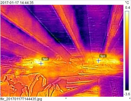
Thermal Infrared camera image showing hot spots in the attic. These came from unsealed electrical boxes located in the ceiling.
Therefore, the first step is to identify all the places where the air leakage occurs, and to then airseal these leaks.
Insufficient insulation.
There are many ways to insulate a home. Underlying all insulation is the reality that non-moving air is a very good insulator. Moving air, on the other hand, is pretty good at transferring heat. So the trick is to capture as much air as possible in a way that prevents it from moving. That’s what the different forms of insulation do, to greater or lesser degrees of effectiveness.
One common measure of insulation effectiveness is the R-value, which is measured by various techniques and published by the manufacturers of the insulation. Just like the car manufacturers who post very nice litres per kilometer ratings to show how energy efficient their cars are, so do insulation manufacturers who post values that are achieved under ideal conditions. Therefore, just because a material is claimed to have an R-value of (say) 4.0/in. doesn’t mean that you will actually achieve that value in practice under realistic conditions.
Another complication in assessing insulation value is the temperature difference between the “inside” and the “outside”. The greater the difference, the greater is the tendency for air to move, because a difference in temperature creates a pressure gradient. So loosely-packed insulation that allows air movement may lose a substantial portion of its insulating value if the temperature difference is large enough.
Insulation near the eaves, where we expect (and want) air movement to occur, will also lose insulating value due to the air movement, unless specific measures are taken to prevent this air from entering the insulation.
One other contributor to loss of insulating value is the presence of moisture in the insulation, which may be due to leakage or condensation. If the leakage was due to an ice dam, then you will understand that this will increase the heat loss, which in turn makes the ice dam worse, which will increase the leakage- a positive feedback loop which is not good.
There are many sources for insulation value information. I will give some links at the end of this post to allow you to do further research. For the time being, let’s make some assumptions, based on published manufacturers’ data. Owens-Corning PINK(R) Fiberglas(R) insulation is given a value of R40 for an 11″ thickness, which works out to about R3.6 per 1 inch. Another manufacturer (ROXUL) lists their ComfortBATT(R) product at R32 for 8″ thickness, giving an R-value of R4 per 1 inch. Keep in mind these values are the values obtained under optimum conditions and if the insulation is NOT laid very carefully to avoid air gaps or compression, then the resulting insulation value is less. Based on what I see in many attics, I’d generally give the effective R-value for such insulation to be somewhere between R2 and R3 per inch, which means that you’re looking at anywhere from 15 inches to 20 inches of insulation to achieve the desired amount.
In some attics, especially near the eaves, you just don’t have enough vertical room to accomodate 15-20 inches of insulation, so it means that along the eaves, you will have more heat loss than perhaps deeper in. The way around this problem is to consider using a product like spray foam (polyurethane or polyisocyanurate) which has a nominal R-value of about R6-R7 per inch, at least in the areas immediately adjacent to the eaves.
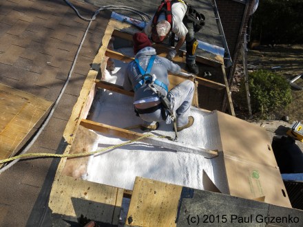
Installation of polyisocyanurate foam at eaves since design of rafters left very little space between the roof and the ceiling at the top plate.
Therefore, the next step is to ensure that you have adequate insulation in all parts of your attic or cold space, and the exact method of achieving this will depend on the existing structure.
Additional sources of heat.
Attics generally sit on top of ceilings, and ceilings are where many people install pot-lights, fans, light fixtures and the like. Unless these were installed using the air-tight and insulated fixtures, these will usually be a source of heat. R-40 may be sufficient insulation to minimize heat loss when the interior temperature is at room temperature, but when the object is hot, then R-40 will not be sufficient (since heat transfer is proportional to the temperature difference).
I was called to deal with a bad ice-damming situation on a roof where there was no prior history of ice-damming. It turned out that the homeowners had an extensive kitchen renovation done and had a number of potlights installed over the sink, stove, and along the windows. Since the roof of that particular house had a relatively low slope and was just above the kitchen, the contractor had not much space in the attic to work in, and ended up installing ventilated pot light fixtures into the ceiling without providing for either air sealing or insulation. This ended up bringing a lot more heat into that part of the roof, partly though air leakage through the ventilated pot light housing, but primarily due to the heat produced by these lights. Since neither insulation nor ventilation was adjusted to cope with this new heat load, the result was a much hotter roof than before, and therefore extensive melting of snow, which froze at the edges of the eaves. Instant ice-dam!

Ice dam created by heat from kitchen renovation (pot lights, insufficient insulation & ventilation)
Another source of heat is the addition of air conditioning equipment into the attic space. Whether it’s the air ducts or the mechanical equipment itself, these are usually much hotter than room temperature, but often are wrapped with less than an inch of insulation. When the heating system is in operation, one of the heat losses that it experiences is into the attic. Passive ventilation, even when up to the code requirement, is not sufficient to evacuate this additional heat.
Air ducts that are not well sealed are another source of heat into the attic. This can be due to inperfect sealing on the air duct joints, or it can be due to insufficient insulation. Both will increase the amount of heat that the ventilation has to dissipate.
Many of these sources of heat can be easily seen in the attic if one uses a thermograph, or thermal infrared camera or sensor. Therefore, this is one of the tools an inspector should use to conduct an inspection, in addition to a detailed visual inspection.
Additions, extensions and renovations.
It is, unfortunately, quite common for additions, extensions and renovations to occur without the builders or contractors paying attention to the maintenance of the integrity of the house envelope, or to take into account the way the insulation and ventilation should be adjusted to reflect the new reality. This can create new cold or hot spots, new areas with air infiltration, and change the overall balance of how heat and airflow work. We’ve seen ice dams form on roofs where there is no history of ice dams, because the ventilation that used to reduce the heat at that location is now cut off by an extension. Even upgrading the windows to more airtight and energy-efficient ones can change how the heat and humidity in the house are affected, with potentially more humidity accumulating, and venting into cold spaces in amounts that cause condensation inside and ice dams outside.
Ventilation issues – blocked or solid soffits.
Many, and probably most homes in our region with sloped roofs rely on intake ventilation from the soffits. With homes constructed since the 1980’s the presence of functioning soffit cavities is quite normal, but for older homes, this can be hit-and-miss. It continues to amaze me how often we find new ventilated soffits installed over solid soffit material. Sometimes there are a few token holes cut out in the original solid soffit, but usually even this very basic step is skipped. This means that a contractor was paid to carry out ventilation improvements, and went through the process of giving the appearance of improving the ventilation, without ensuring that the ventilation was actually improved.
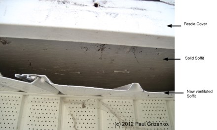
Example of solid soffit (as was customary for construction until about 1970’s) that had ventilated soffits installed without any actual venting improvement.
Other times, the soffits are blocked by insulation, or wood blocking between the rafters.
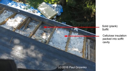
Example of soffit cavity filled with insulation. Given that the soffit is exterior to the house, the insulation in that space gives no benefit to the house.
Blocked access of soffit air into the attic
Whatever the reason, if the air channel from the soffit cavity into the attic is not open sufficiently (a minimum is 1″ of vertical air space between the insulation and the roof deck, but more is better), then the air circulation in the attic will be much less than should be the case.
We often find various obstructions which prevent the soffit air (assuming the soffits are open and ventilated) from entering the attic. These include insulation pushed against the roofing deck (cutting out any air flow), insulation baffles that are poorly installed and block the air channel, and wood blocking that prevents any air access.
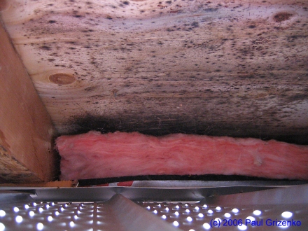
Example of air channel blockage by poorly-installed insulation.
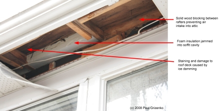
Example of situation where the causes of the ice-damming were not understood, and client kept blaming the roof covering for poor performance whereas the problem was the lack of air intake and attic ventilation.
Compromised ventilation due to venting cross-circuits.
Another thing that reduces the effectiveness of soffit ventilation is the phenomenon of cross-circuit ventilation. That can happen when there are multiple entry and exit points for air on a roof – for example soffit intakes, combined with some low-profile vents, gable vents, and Maximum vents along the top of the roof. Since the hot air will rise to the highest point of the roof, vents at those locations will serve as the outlets. Air escaping through these high vents will need to be replaced by new air. The source which will be used is always the one with the least resistance to air flow, and this tends to be the very open and easily accessible gable vent. The soffit vents give airflow the most resistance, and will provide very little air if there are alternative sources.
Even the presence of vents at lower levels than the highest vents, may cause them to reverse the intended flow, and have them become inlet vents. Now you know why some vents “leak” while others don’t.
Roofing geometry that frustrates ventilation efforts
In general, complex roof lines complicate the ability of a roof to ventilate. Consider an L-shaped roof with a large valley on one side and a large hip on the other. Since air flow tends to be linear, from the low point to the high point, the areas under a valley are almost never well vented (due no no intake), as are the areas under the hips (no exit).
The presence of skylights also has a big effect on air circulation, as the skylights (and their attendant insulation) usually block a significant area of roof. The area below the skylight has no exit, and the area above the skylight has no intake.
A similar phenomenon exists with dormers which block off the area below them from air circulation.
There are a number of other roof designs that make getting balanced ventilation a difficult proposition UNLESS the person planning the ventilation is taking the roof geometry into account. This leads to the next topic,
Poor distribution and location of outlet vents.
Vents are generally not considered to be aesthetically-pleasing aspects of roofing appearance, and consequently they tend to be hidden somewhere behind the roofline, at the back of the house. Depending on the roof geometry, that may not be, in fact, the best way of distributing the vents for them to work properly. Furthermore, the type of vent used and its location should also take into account external factors such as wind direction and the amount of snow accumulation in your area and on your roof. If your roof consistently has a snowdrift building up in a certain area due to the roof shape and prevailing winds, it is rather foolish to locate an outlet vent in that location.
From time to time, we see vents places on the lower parts of the roof, in conjunction with vents higher up, together with soffit vents and gable vents, presumably under the philosophy that more is better. Unfortunately, this ignores basic physics. Flow tends to follow the least resistance, and some of these vents become intake vents instead of outlet vents. If your vents are “leaking” there’s a pretty good chance that the real fault is the poor location of the vents which causes them to aspirate rainwater due to them acting as air intakes.
Use of attic space for storage
Everyone need more space to store their stuff. A common place to do this is in the attic. While this solves one problem, it can create another. Depending on how much stuff you put up there, you can disrupt the airflow and turn your ventilated attic into a poorly-vented condensation trap. If you MUST do this, set up a platform above the insulation (so not to compress it), and do it at the middle part of the attic, away from the airflow that you should have from the vented soffit to the vented ridge. Also pay attention to the attic trap door and ensure it is both properly air-sealed, and adequately insulated.
Summary (or the TL;DR synopsis)
- Eliminate (or at least reduce) air leakage into the attic.
- Eliminate (as much as possible) heat sources.
- Increase insulation to have effectively a minimum of R40, taking into account the roof geometry
- Ensure that your ventilation is at least 1:300 ratio of ventilation to attic area (1:150 or better if complex roofline or complicated air flow)
- Call an expert or consultant (like me) to verify the true state of your roof and identify the issues. You can’t fix what you haven’t diagnosed properly.
Links to further information
Ice Dams:
Building Science video (youtube) on Ice Dams
Building Science Corp. article on Ice Dams
Building Science Corp. Insight article on Ice Dams
Article on Ice Dams in “Real Estate” publication of Boston Globe
Insulation
Wikipedia article on Building Insulation
Jon Eakes post on Insulation for Roofs
The links below are from (some) companies manufacturing insulation. They are examples of insulation supplies, and the list is neither comprehensive, nor an endorsement. I show their links as the source from where I got the insulation values of their products that I referenced in the insulation discussion.
Roxul Residential Insulation Overview page
Ventilation
Jon Eakes article on soffit venting
Building Science Corp. Article on roof Venting
Building Science Corp. Digest article on Roof Venting
Contact for Consultation:
If you are located in the Greater Montreal area, and have been having issues with Ice Dams that don’t seem to get solved, call me for an appointment to set up a consultation. Consultations are charged on an hourly basis of $80/hr, with the clock starting at the point I leave the office to drive to your location, and stopping when I return back after the consultation. If I do reports or additional work on your behalf, then that time will be charged as incurred, with a minimum charge of 1 hour, and time rounded up to the nearest half hour. An average consultation appointment is from 2-3 hours on site, and the average consultation charge is $240-$320 (taxes extra). This is usually sufficient for a preliminary investigation and a good idea of what to focus on. An in-depth consultation requiring the development of remedial work scope can range to several days of effort and documentation.


(c) 2017 Paul Grizenko
